TECHNICAL NOTES
89
7. Optimal usage of high-power LED devices requires careful design by
the end-user to optimize heat dissipation, such as increasing the size
of the metal backing around the soldering pad. Refer to the product
datasheet for specific design recommendations regarding heat
dissipation.
Restrictions on Product Use
Storage Control
For SMD Products
1. Before a sealed moisture barrier bag (MBB) is opened, contained
LEDs shall be kept in an environment with temperature below 40°C
and humidity below 90% RH. MBB shall be kept sealed until LEDs
contained in the bag are ready to be used. Once MBB is opened, it
shall be stored in an environment with temperature range of
5°C~30°C and humidity below 60% RH.
2. Once MBB is opened, all contained LEDs shall complete soldering
process within the specified time frame according to the conditions
labeled on Kingbright MBB.
3. When the 10% spot of a humidity indicator card (HIC) from MBB
indicates wet, the contained LEDs shall be baked according to the
baking conditions labeled on Kingbright MBB before mounting.
For Through-Hole Products
1. Avoid continued exposure to the condensing moisture environment and
keep the product away from rapid transitions in ambient temperature.
2. LEDs should be stored with temperature ≤30°C and relative humidity
< 60%.
3. Product in the original sealed package is recommended to be assembled
within 72 hours of opening. Product in opened package for more than a
week should be baked for 30 (+10/-0) hours at 85 ~ 100°C.
4. The LED leadframe surface is plated with silver. When the leadframe is
stored under high-humidity environments, or exposed to certain chemical
elements or gases, the surface may become discolored. Please maintain
the cleanliness of the storage environment.
5. If the storage conditions do not meet specification standards, the
component pins may become oxidized requiring re-plating and re-sorting
before use. Suggest customers consume LEDs as soon as possible, and
avoid long-term storage of large inventories.
6. The size of the nozzle should be as large as possible if the tape is not
involved.
7. The LEDs should not be exposed to an environment where high level
of moisture or corrosive gases are present.
8. Prolonged reverse bias should be avoided, as it could cause metal
migration, leading to an increase in leakage current or causing a short
circuit.
9. Excess driving current and/or operating temperature higher than
recommended conditions may result in severe light degradation or
premature failure.
10. It is not recommended to assemble LEDs of different color or intensity
bins together, as there may be perceivable color or intensity variation.
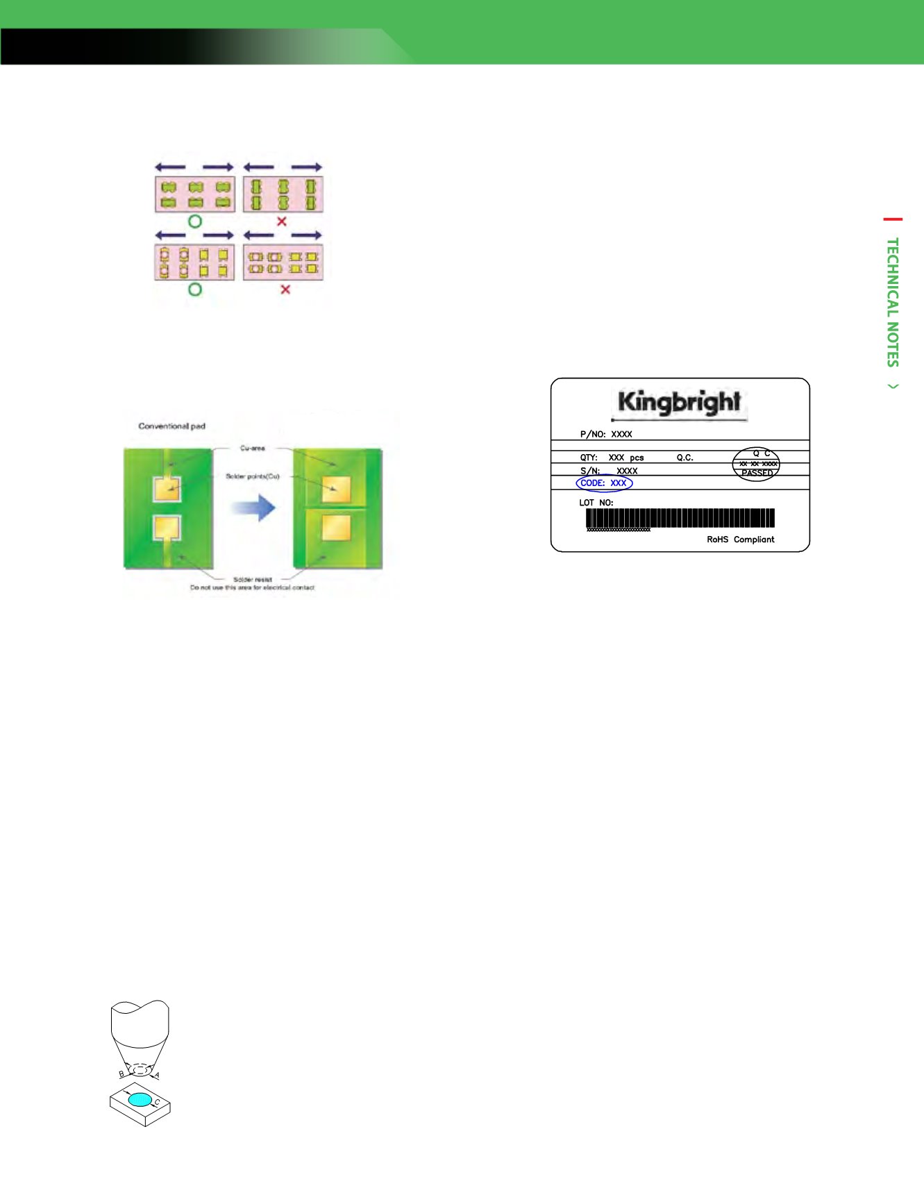
Each bag contains parts from the same bin code. The bin code is
printed on the bag’s label as below.
1. Not all devices and product families are available in every country.
2. The light output from UV, blue, white, and other high-power LEDs may
cause injury to the human eye when viewed directly.
3. LED devices may contain gallium arsenide (GaAs) material. GaAs is
harmful if ingested. GaAs dust and fumes are toxic. Do not break, cut,
or pulverize LED devices. Do not dissolve LEDs in chemical solvents.
4. Semiconductor devices can fail or malfunction due to their sensitivity
to electrical fluctuation and physical stress. It is the responsibility of the
user to observe all safety standards when using Kingbright products, in
order to avoid situations in which the malfunction or failure of a
Kingbright product could cause injury, property damage, or the loss of
human life. In developing designs, please insure that Kingbright
products are used within specified operating conditions as set forth in
the most recent product specification datasheet.
5. For LEDs with silicone encapsulation such as the AA and AT series, the
outer diameter of the pick-up nozzle must be longer than that of the
LED’s light emitting area. i. e. A >C, and B shall be shorter than the
width of the LED.
A is the outer diameter pick-up nozzle
B is the inner diameter of the nozzle
C is the diameter of lens
6. During soldering, SMD components should be mounted such that the
leads are placed perpendicular to the direction of PCB travel to ensure
the solder on each lead melts simultaneously during reflow.
Pad design for
improved heat dissipation
Application Notes


